Decoding Circuit Whispers: Mastering Electronic Component Symbols
Ever wondered how engineers communicate the intricate language of electronics? The answer lies in a visual vocabulary: electronic component diagram symbols. These symbolic representations are the building blocks of circuit diagrams, enabling engineers to design everything from simple LED circuits to complex microprocessors. They are the shorthand of electronics, conveying complex information with concise clarity.
Electronic component symbols provide a standardized way to represent various electronic components in a schematic diagram. Without a common visual language, deciphering circuit designs would be a chaotic mess, prone to misinterpretations and potentially disastrous outcomes. These symbols act as a universal translator, fostering collaboration and innovation across the electronics industry.
The genesis of electronic component diagram symbols can be traced back to the early days of electrical engineering. As circuits became more complex, the need for a standardized system of representation arose. Early symbols were often crude pictorial representations of the components themselves. Over time, these evolved into the more abstract and standardized symbols we use today, governed by organizations like the IEEE (Institute of Electrical and Electronics Engineers) and IEC (International Electrotechnical Commission).
The importance of understanding these symbols cannot be overstated. They are fundamental to designing, analyzing, and troubleshooting electronic circuits. Imagine trying to build a house without blueprints. Similarly, attempting to construct a circuit without a proper schematic diagram, utilizing these crucial symbols, would be an exercise in futility. These visual representations are essential for effective communication and collaboration among engineers, technicians, and hobbyists alike.
One of the main issues related to electronic component diagram symbols is maintaining consistency and adhering to standards. With the ever-evolving landscape of electronics, new components and symbols are constantly being introduced. Ensuring that everyone uses the same symbolic language is crucial for avoiding confusion and errors in circuit design and analysis.
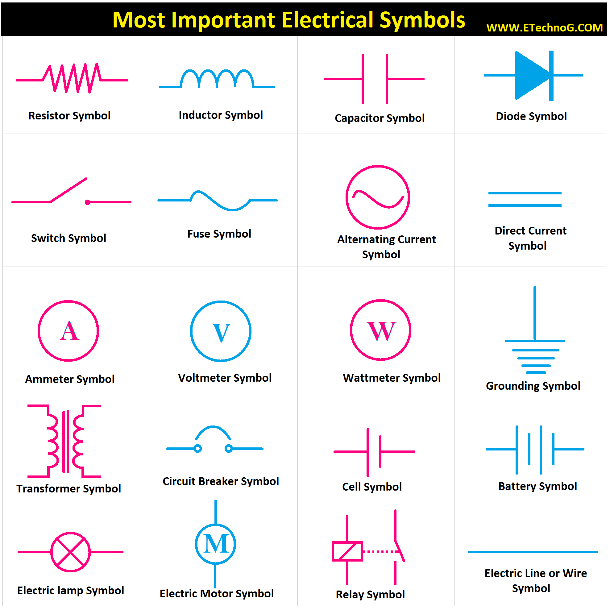
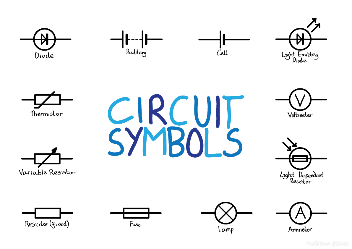
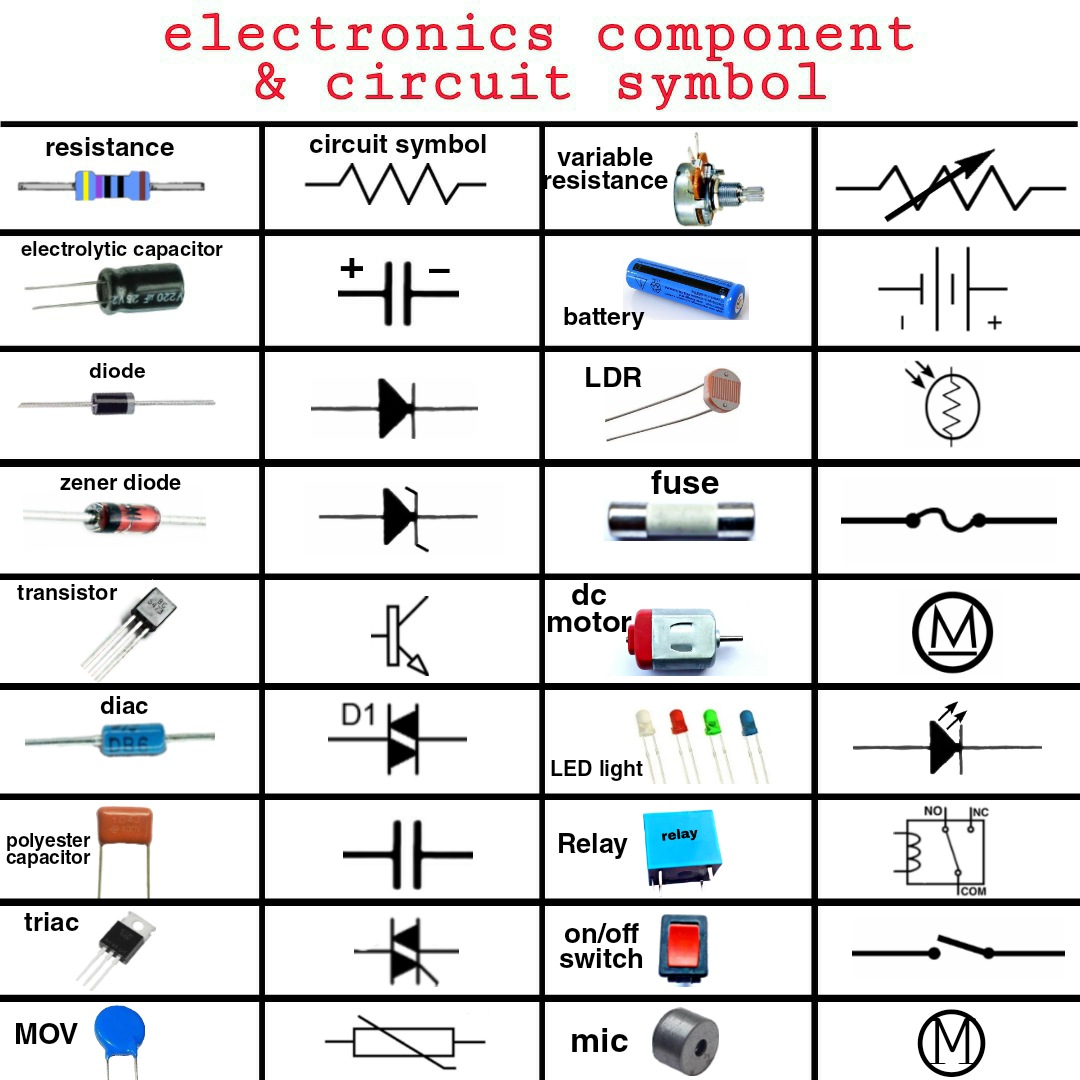
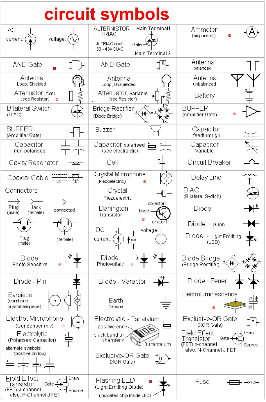
For example, a resistor, which impedes the flow of current, is represented by a zig-zag line. A capacitor, which stores electrical energy, is depicted by two parallel lines. These simple yet powerful symbols encapsulate the function of the components they represent.
Benefits of using standardized electronic component symbols are threefold. Firstly, they facilitate clear communication, enabling engineers worldwide to understand circuit designs regardless of language barriers. Secondly, they streamline the design process, allowing engineers to quickly and efficiently create and modify circuit diagrams. Lastly, standardized symbols aid in troubleshooting and repair, as technicians can readily identify components and their connections within a circuit.
Creating a successful circuit design involves a systematic approach. Start by defining the circuit's purpose and specifications. Next, select the appropriate electronic components based on their functions. Then, using standardized symbols, draw a schematic diagram of the circuit. Finally, build and test the circuit, making adjustments as needed. Examples of successful implementations of these symbols can be found in countless electronic devices, from smartphones and laptops to medical equipment and industrial automation systems.
Advantages and Disadvantages of Electronic Component Diagram Symbols
| Advantages | Disadvantages |
|---|---|
| Clear Communication | Need for Standardization |
| Simplified Design Process | Potential for Misinterpretation if not standardized |
| Efficient Troubleshooting | Keeping up with Evolving Symbols |
Best practices for implementing electronic component diagram symbols include using clear and concise labels, maintaining consistent spacing and orientation, and adhering to established standards. Always double-check your work for errors and ensure that the diagram accurately reflects the intended circuit design.
Real-world examples of these symbols in action can be found in the schematics of any electronic device. From the simple circuit of a flashlight to the complex circuitry of a computer, these symbols are the universal language that brings electronic designs to life.
Challenges in using electronic component diagram symbols can include keeping up with new symbols, ensuring consistent interpretation, and managing complex diagrams. Solutions to these challenges include using updated software tools, referencing standardized documentation, and employing hierarchical design approaches.
Frequently Asked Questions about electronic component diagram symbols include: What are the most common symbols? Where can I find a comprehensive list of symbols? How do I use these symbols in circuit design software? What are the different standards for electronic component symbols? How do I interpret complex diagrams? What are the best resources for learning about electronic component symbols? How can I stay updated on new and evolving symbols? What are some common mistakes to avoid when using these symbols?
Tips and tricks for working with electronic component diagram symbols include using online symbol libraries, practicing with simple circuits, and joining online communities for support and guidance.
In conclusion, electronic component diagram symbols are the cornerstone of electronic design and communication. They provide a standardized language that enables engineers and technicians to design, analyze, and troubleshoot complex circuits with clarity and efficiency. From their humble beginnings as pictorial representations to the standardized symbols we use today, they have played a vital role in the advancement of electronics. Mastering these symbols is essential for anyone working in the field of electronics, from seasoned engineers to aspiring hobbyists. By understanding their history, importance, and practical applications, you can unlock the power of these symbols and navigate the fascinating world of circuit design with confidence. Embrace this visual language, stay updated with evolving standards, and contribute to the ever-evolving landscape of electronics. Start exploring the world of electronic component diagram symbols today, and discover the power of concise communication in circuit design.
Decoding red sherwin williams traffic paint
Conquering fc 24 live editor glitches
Boat lift motors powering your waterfront lifestyle


.jpg)